Rotary Kilns
For measuring support rollers, tyres and shell diameter in cement plants, sponge iron plants and other rotary kiln installations.
A practical diameter measuring instrument for large rotating cylinders such as rotary kiln support rollers, kiln tyres, shells, rotary dryer rollers and ball mill trunnions.
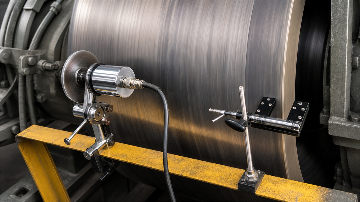
The Diameter Measuring Wheel is used like a large industrial caliper to measure the diameter of rotating cylindrical surfaces that are exposed to wear during operation. The measured diameter helps maintenance teams decide whether re-machining, replacement or fine-tuning adjustment is required to keep the kiln, dryer or ball mill axis properly aligned.
PRICE
₹5,00,000 + GST
Base product price. GST extra as applicable.
Floor Tech Kiln Measurement is the specialised rotary equipment measurement product division of Floor Tech PVC Fabricators, Chennai.
The division focuses on diameter measurement systems for large rotating cylindrical equipment, including rotary kiln support rollers, kiln tyres, shells and other suitable industrial measurement applications.
The Diameter Measuring Wheel is a measuring instrument used to check the diameter of large rotating cylinders. It is suitable for rotary kiln support rollers, kiln tyres, kiln shells, rotary dryer rollers, dryer tyres, dryer shells, ball mill trunnions and similar rotating cylindrical parts.
During service life, these components are subjected to wear and tear. Diameter variation can affect contact condition, alignment and long-term running performance. By measuring the diameter, the maintenance team can take fact-based decisions for re-machining, replacement or fine adjustment.
For measuring support rollers, tyres and shell diameter in cement plants, sponge iron plants and other rotary kiln installations.
For measuring support rollers, tyres and shell diameter in rotary dryer systems where cylindrical surfaces wear during operation.
For measuring trunnions, tyres and shell diameter where large cylindrical rotating surfaces need inspection.
For collecting diameter data required for re-machining decisions, replacement planning, fine-tuning adjustments and alignment correction.
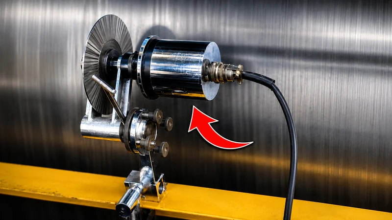
The instrument works by keeping a spring-loaded measuring wheel in contact with the cylindrical surface to be measured. The measuring wheel rotates along with the surface and the encoder sends pulses to the display controller unit.
A magnetic trigger pointer is mounted on the rotating cylinder. A light barrier sensor is fixed on a stable, non-moving surface. The magnetic trigger and the light barrier sensor are positioned so that the trigger passes through the sensor during rotation.
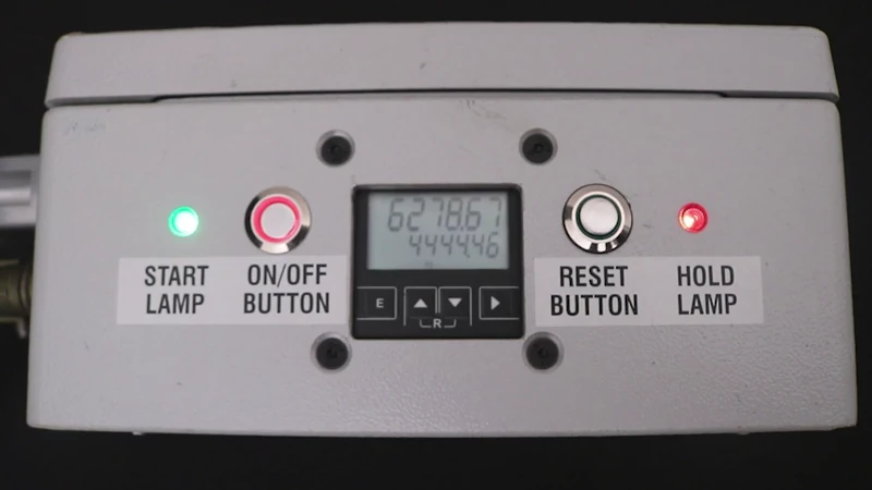
When the first trigger pulse is received, the controller starts the measurement. When the second trigger pulse is received after one full rotation, the controller stops the measurement and displays the final diameter on the display unit.
Mount the measuring wheel on a stable fabricated platform near the roller or tyre.
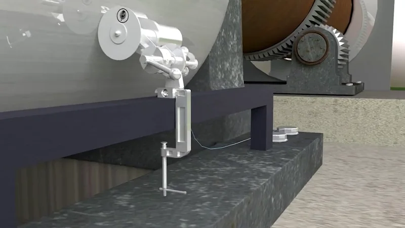
Keep the wheel in proper contact with the rotating cylindrical surface using the spring loading lever.
Fix the magnetic trigger pointer on the rotating cylinder.
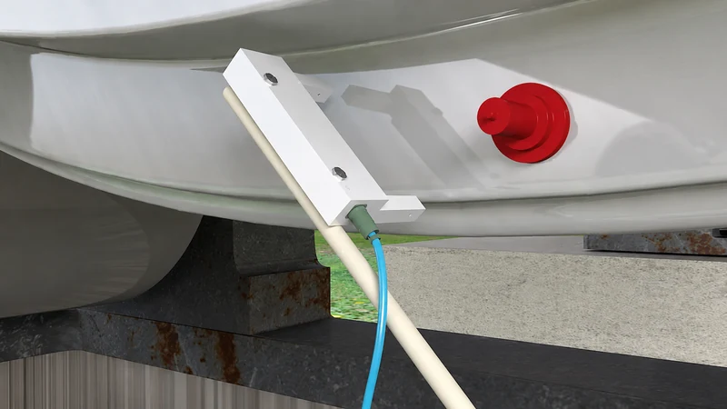
Position the light barrier sensor so the trigger passes through it.
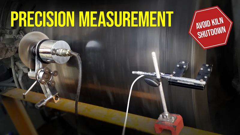
Connect the measuring wheel cable and light barrier sensor cable to the controller unit.
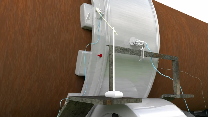
Start the controller and take the diameter reading after one full rotation.
The Diameter Measuring Wheel is supplied in a durable flight case box suitable for safe handling and transport.
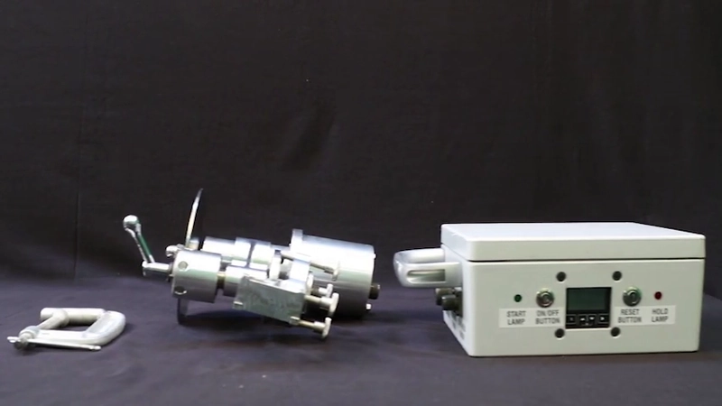
The measuring wheel is the main contact component of the instrument. It is kept in contact with the cylindrical surface and rotates along with the surface. It includes a hardened steel wheel, encoder, connector, spring suspension, fine tuning thumb screws and G clamp arrangement.
The display controller unit receives signals from the measuring wheel and the light barrier sensor. It shows the final diameter reading after the complete measuring cycle.
The light barrier sensor provides the precise start and stop trigger pulse for each revolution. It works with the magnetic flag switch and sends the trigger signal to the controller unit.
The magnetic flag switch is mounted on the rotating cylinder. It passes through the light barrier sensor and triggers the measurement cycle.
Align the light barrier fork so that the magnetic flag switch passes through it. When the light beam is interrupted by the magnetic flag switch, the light barrier sensor sends an electrical pulse to the controller unit.
Mount the measuring wheel using the G clamp provided with the tool kit. Fix it firmly to a fabricated platform near the support roller or tyre. Ensure that the contact surfaces are clean and stable.
Depending on the measurement purpose, the wheel can be placed at different positions along the width of the roller or tyre. For kiln axis alignment or general wear checking, one central reading is normally taken. For cylindricity checking, multiple readings are taken across the width.
Insert the cable connectors into the corresponding ports on the controller unit. Make sure the connectors are aligned correctly and inserted firmly.
After the setup is completed, the controller unit waits for the first trigger from the light barrier sensor. When the magnetic flag switch passes through the light barrier sensor, the first trigger is given to the controller unit and the start lamp glows.
The reading starts and the controller waits for the second trigger. The second trigger occurs after one complete rotation of the cylindrical surface. When the second trigger is received, the stop lamp glows and the final diameter is displayed on the controller unit.
Diameter measurement helps identify changes in roller, tyre and shell diameter so that alignment corrections can be planned properly.
Regular measurement helps maintenance teams understand wear patterns on support rollers, tyres, shells and trunnions.
Taking readings at multiple positions across the width helps identify diameter variation and surface condition.
Measurement data helps decide whether a roller, tyre or trunnion requires re-machining, replacement or fine adjustment.
The instrument gives maintenance teams a practical measurement method instead of relying only on visual inspection.
In rotary kilns, rotary dryers and ball mills, support rollers, tyres, shells and trunnions gradually wear during operation. Even small changes in diameter can affect contact condition, running behaviour and alignment decisions. The Diameter Measuring Wheel provides a practical way to measure these large cylindrical parts during maintenance inspection.
This instrument is useful for plant maintenance teams who need diameter data for kiln alignment, tyre checking, support roller inspection, cylindricity checking and re-machining planning. It can be used for rotary kiln diameter measurement, rotary dryer diameter measurement and ball mill trunnion measurement applications.
See the Diameter Measuring Wheel demonstration video to understand the mounting arrangement, sensor trigger and measurement procedure.
Download the Diameter Measuring Wheel product catalogue.
Download CatalogueWatch product video on YouTube.
Watch VideoIt is used to measure the diameter of large rotating cylindrical surfaces such as rotary kiln support rollers, kiln tyres, rotary dryer rollers, shells and ball mill trunnions.
Yes. It is suitable for rotary kiln support rollers, tyres and shell diameter measurement.
Yes. It can be used for rotary dryer support rollers, tyres and shell measurement.
Yes. It can be used for ball mill trunnions, tyres and shell diameter measurement.
Diameter measurement helps identify wear, cylindricity variation and dimensional changes. This information is useful for re-machining decisions, replacement planning and alignment correction.
The measuring wheel rotates in contact with the cylindrical surface. A magnetic flag switch and light barrier sensor provide start and stop trigger pulses for one full rotation. The controller then displays the final diameter.
The main parts are the spring loaded measuring wheel with encoder, display controller unit, light barrier sensor, magnetic flag switch, cables, G clamp and flight case box.
Yes. The instrument is supplied in a durable flight case box for safe transport and storage.
Contact us for Diameter Measuring Wheel supply, technical discussion, quotation and product details. Share your application, cylinder type, approximate diameter, site location and required quantity.